
Technology aimed at the control of a battery pack—an assembly of battery cells, electrically arranged in a row x column matrix configuration to enable delivery of targeted range of voltage and current for a duration of time against expected load scenarios—is known as battery management system (BMS). Typically, a BMS offers monitoring including:
- Examining the battery.
- Provide protection for batteries.
- Applying operational state estimation for the battery.
- Always improving the performance of batteries.
- Notifying outside systems operational status.
Here, the word “battery” refers to the whole pack; yet, in the overall battery pack assembly, the monitoring and control functions are especially applied to individual cells, or groups of cells called modules. From computers to electric cars, many consumer devices including battery packs use lithium-ion rechargeable cells because of their maximum energy density. Although they function well, if run outside of a usually limited safe operating area (SOA), they may be fairly merciless with results ranging from impairing the battery performance to absolutely disastrous consequences. The BMS undoubtedly has a demanding job description, and its total complexity and supervision spread may encompass numerous disciplines such as electrical, digital, control, thermal, and hydraulic.
How Do Battery Management Systems Work?
Battery management solutions do not have a predefined or unique set of criteria that must be applied. The technological design scope and realized features often connect with:
- The expenses, complexity, and size of the battery pack.
- Application of the battery and any safety, longevity, and warranty considerations.
- Certification criteria from different government rules where fees and penalties are crucial if insufficient functional safety measures are in place.
There are several BMS design aspects, with battery pack protection management and capacity management being two crucial characteristics. We’ll examine how these two features function here. Battery pack protection management includes two important arenas: electrical protection, which entails not allowing the battery to be harmed by use outside its SOA, and thermal protection, which comprises passive and/or active temperature regulation to keep or bring the pack within its SOA.
Electrical Management Protection: Current
Monitoring battery pack current and cell or module voltages is the key to electrical protection. The electrical SOA of every battery cell is restricted by current and voltage. Figure 1 displays a typical lithium-ion cell SOA, and a well-designed BMS will preserve the pack by prohibiting operating beyond the manufacturer’s cell ratings. In many circumstances, more derating may be done to live inside the SOA safe zone in the purpose of boosting extended battery duration.
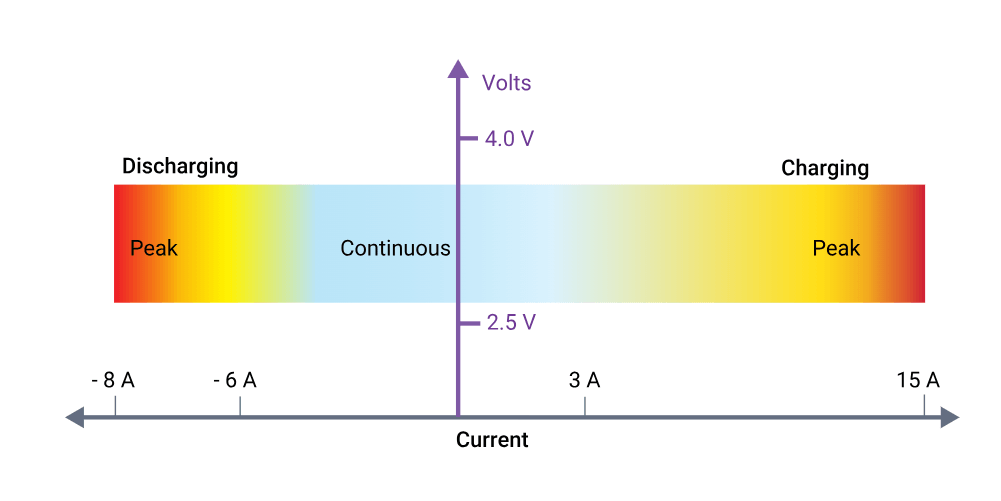
Lithium-ion cells have different current limits for charging than for discharging, and both modes can handle higher peak currents, albeit for short time periods. Battery cell manufacturers usually specify maximum continuous charging and discharging current limits, along with peak charging and discharging current limits. A BMS providing current protection will certainly apply a maximum continuous current. However, this may be preceded to account for a sudden change of load conditions; for example, an electric vehicle’s abrupt acceleration. A BMS may incorporate peak current monitoring by integrating the current and after delta time, deciding to either reduce the available current or to interrupt the pack current altogether. This allows the BMS to possess nearly instantaneous sensitivity to extreme current peaks, such as a short-circuit condition that has not caught the attention of any resident fuses, but also be forgiving to high peak demands, as long as they are not excessive for too long.
Electrical Management Protection: Voltage
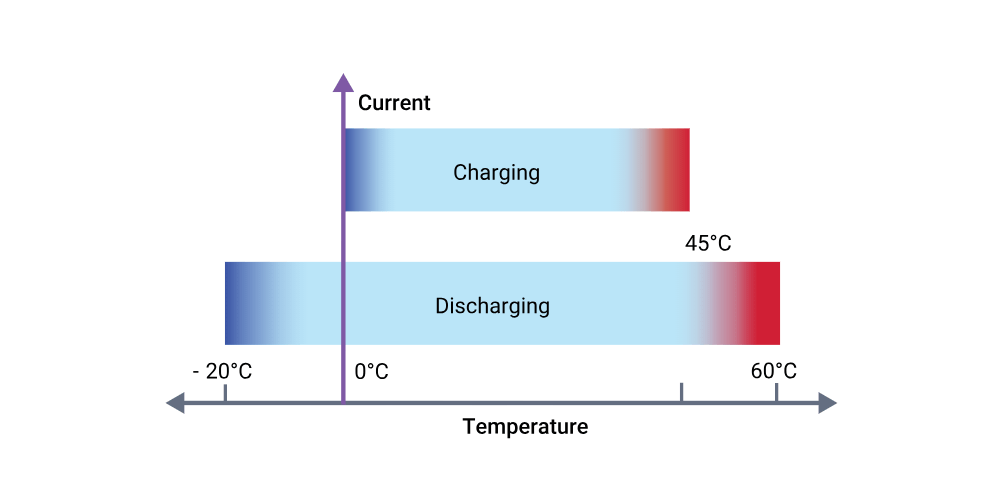
Figure 2 shows that a lithium-ion cell must operate within a certain voltage range. These SOA boundaries will ultimately be determined by the intrinsic chemistry of the selected lithium-ion cell and the temperature of the cells at any given time. Moreover, since any battery pack experiences a significant amount of current cycling, discharging due to load demands and charging from a variety of energy sources, these SOA voltage limits are usually further constrained to optimize battery lifespan. The BMS must know what these limits are and will command decisions based upon the proximity to these thresholds. For example, when approaching the high voltage limit, a BMS may request a progressive decrease in charging current, or may that the charging current be halted entirely if the limit is reached. However, this restriction is frequently complemented by extra intrinsic voltage hysteresis considerations to minimize control chatter regarding the shutdown threshold. On the other hand, when approaching the low voltage limit, a BMS will request that key active offending loads reduce their current demands. In the case of an electric vehicle, this may be carried out by reducing the allowed torque available to the traction motor. Of course, the BMS must make safety considerations for the driver the highest priority while protecting the battery pack to prevent permanent damage.
Thermal Management Protection: Temperature
At face value, it may appear that lithium-ion cells have a wide temperature operating range, but overall battery capacity diminishes at low temperatures because chemical reaction rates slow down remarkably. With respect to capability at low temperatures, they do perform much better than lead-acid or NiMh batteries; however, temperature management is prudently essential since charging below 0 °C (32 °F) is physically problematic. The phenomena of plating of metallic lithium may occur on the anode during sub-freezing charging. This is irreversible damage and not only results in lower capacity, but cells are more sensitive to failure if exposed to vibration or other stressful situations. A BMS may manage the temperature of the battery pack by heating and cooling.
Realized thermal management is fully reliant upon the size and cost of the battery pack and performance targets, design requirements of the BMS, and product unit, which may include consideration of desired geographic location (e.g. Alaska vs Hawaii). Regardless of the heater type, it is often more effective to take energy from an external AC power source, or an alternate resident battery purposed to run the heater when required. However, if the electric heater has a moderate current requirement, energy from the main battery pack may be drained to heat itself. If a thermal hydraulic system is utilized, then an electric heater is used to heat the coolant which is pumped and dispersed throughout the pack assembly.
BMS design experts definitely have tricks of their design trade to drip thermal energy into the pack. For example, different power electronics within the BMS devoted to capacity management may be switched on. While not as efficient as direct heating, it may be used nevertheless. Cooling is especially critical to reduce the performance loss of a lithium-ion battery pack. For example, suppose a certain battery functions optimum at 20°C; if the pack temperature raises to 30°C, its performance efficiency might be lowered by as much as 20%. If the pack is repeatedly charged and recharged at 45°C (113°F), the performance loss might increase to a whopping 50%. Battery life may also suffer from early aging and degeneration if repeatedly exposed to high heat production, especially during quick charging and discharging cycles. Cooling is normally performed by two ways, passive or active, and both strategies may be applied. Passive cooling depends on movement of air flow to cool the battery. In the case of an electric car, this suggests that it is merely traveling down the road. However, it may be more complex than it seems, since air speed sensors might be connected to strategically auto-adjust deflective air dams to optimum air flow. Implementation of an active temperature-controlled fan may assist at low speeds or when the vehicle has stopped, but all this can do is to equalize the pack with the surrounding ambient temperature. In the case of a blistering hot day, this might raise the initial pack temperature. Thermal hydraulic active cooling can be designed as a complementary system, and typically utilizes ethylene-glycol coolant with a specified mixture ratio, circulated via an electric motor-driven pump through pipes/hoses, distribution manifolds, a cross-flow heat exchanger (radiator), and cooling plate resident against the battery pack assembly. A BMS monitors the temperatures throughout the pack, and open and shuts numerous valves to keep the temperature of the total battery within a small temperature range to guarantee optimum battery performance.
Capacity Management
Maximizing a battery pack capacity is perhaps one of the most critical battery performance characteristics that a BMS delivers. If this maintenance is not completed, a battery pack may ultimately make itself worthless. The basis of the problem is that a battery pack “stack” (series array of cells) is not precisely equal and naturally has somewhat varied leakage or self-discharge rates. Leakage is not a manufacturer fault but a battery chemical property, however it may be statistically effected by minute manufacturing process differences. Initially a battery pack may contain well-matched cells, but with time, the cell-to-cell similarity increasingly diminishes, not only owing to self-discharge, but also influenced by charge/discharge cycles, increased temperature, and general calendar aging. With that acknowledged, remember previously the statement that lithium-ion batteries perform excellently, but may be fairly harsh if handled outside a tight SOA. We heard before about essential electrical protection since lithium-ion batteries do not cope well with over-charging. Once completely charged, they cannot receive any more current, and any extra energy poured into them becomes transmuted in heat, with voltage potentially growing fast, maybe to lethal levels. It is not a healthy environment for the cell and may cause irreversible damage and harmful operating circumstances if it persists.
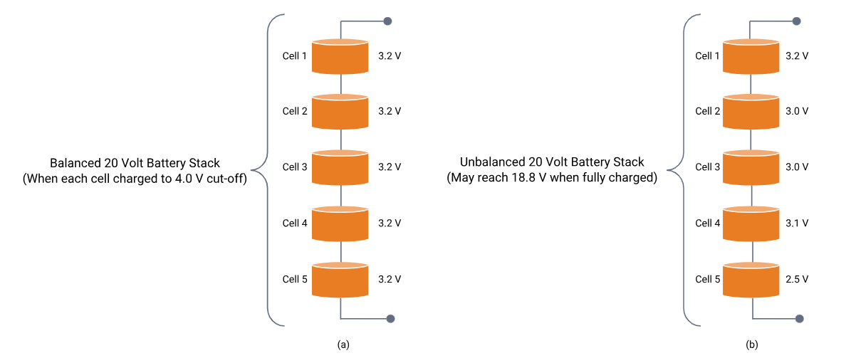
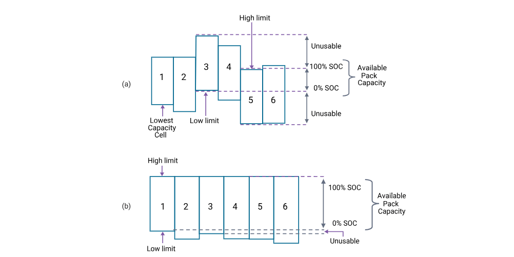
The battery pack series cell array is what controls the total pack voltage, and mismatch between neighboring cells poses a challenge when trying to charge up any stack. Figure 3 demonstrates why this is true. If one has a perfectly balanced set of cells, everything is well since each will charge up in equal way, and the charging current may be turned off when the higher 4.0 voltage cut-off threshold is achieved. However, in the imbalanced case, the top cell will reach its charge limit early, and the charging current has to be interrupted for the leg before other underneath cells have been charged to maximum capacity.
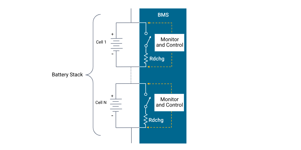
The BMS is what steps in and saves the day, or the battery pack in this instance. To demonstrate how this works, a vital concept has to be stated. The state-of-charge (SOC) of a cell or module at a particular moment is proportional to the charge available compared to the total charge when completely charged. Thus, a battery that dwells at 50% SOC suggests it is 50% charged, which is analogous to a fuel gauge figure of merit. BMS capacity management is all about balancing the fluctuation of the SOC across each stack in the pack assembly. Since the SOC is not a directly quantifiable number, it may be calculated by numerous approaches, and the balancing scheme itself typically falls into two primary groups, passive and active. There are various kinds of themes, and each variety has merits and downsides. It’s up to the BMS design engineer to determine which is ideal for the specific battery pack and its application. Passive balancing is the simplest to apply, as well as to convey the overall balance principle. The passive technique enables every cell in the stack to have the same charged capacity as the weakest cell. Using a relatively modest current, it transfers a tiny amount of energy from high SOC cells throughout the charging cycle such that all cells charge to their maximum SOC. Figure 4 depicts how this is performed by the BMS. It monitors each cell and utilizes a transistor switch and a suitably sized discharge resistor in parallel with each cell. When the BMS feels a specific cell is reaching its charge limit, it will divert surplus current around it to the next cell below in a top-down method.
The balancing process endpoints, before and after, are represented in Figure 5. In essence, a BMS balances a battery stack by enabling a cell or module in a stack to perceive a different charging current than the pack current in one of the following ways:
- Removal of charge from the highest charged cells, which offers headroom for further charging current to avoid overcharging, and permits the less charged cells to receive more charging current.
- Redirection of part or virtually all of the charging current around the highest charged cells, so enabling the less charged cells to receive charging current for a longer period of time.
Types of Battery Management Systems
Battery management systems range from simple to complex and can embrace a wide range of different technologies to achieve their prime directive to “take care of the battery.” However, these systems can be categorized based upon their topology, which relates to how they are installed and operate upon the cells or modules across the battery pack.
Centralized BMS Architecture
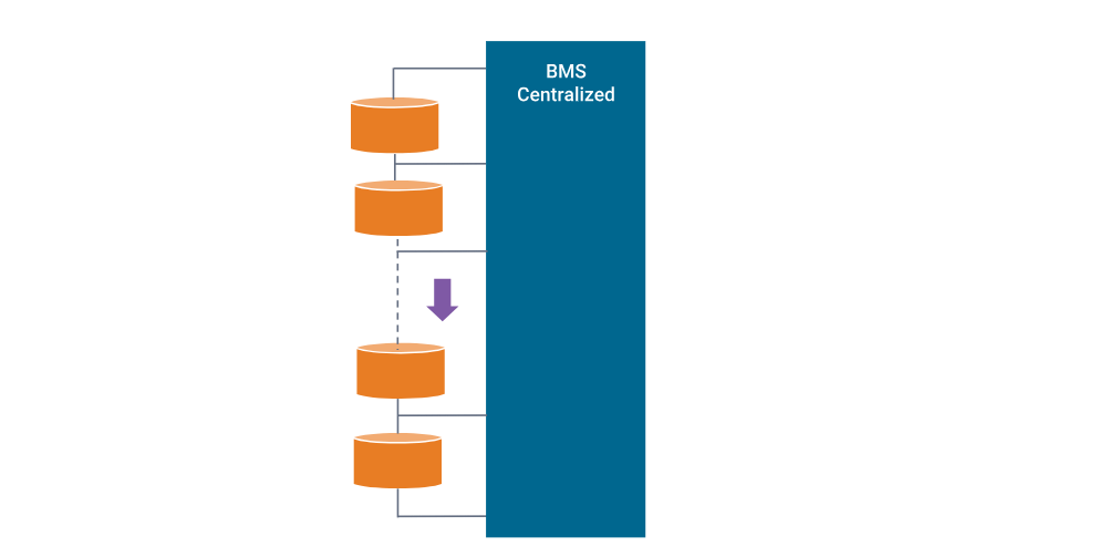
Has one central BMS in the battery pack assembly. All the battery packages are linked to the central BMS directly. The construction of a centralized BMS is presented in Figure 6. The centralized BMS offers certain benefits. It is more compact, and it tends to be the most affordable as there is just one BMS. However, there are downsides to a centralized BMS. Since all the batteries are linked to the BMS directly, the BMS requires a number of ports to connect with all the battery packages. This leads to tons of cables, cabling, connections, etc. in big battery packs, which complicates both diagnosis and maintenance.
Modular BMS Topology
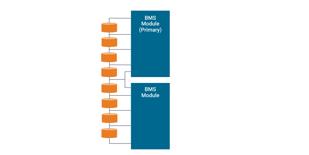
Similar to a centralized approach, the BMS is separated into many replicated modules, each having a specialized bundle of wires and connects to an adjacent allocated piece of a battery stack. See Figure 7. In certain circumstances, these BMS submodules may live under a major BMS module supervision whose job is to monitor the state of the submodules and connect with peripheral equipment. Thanks to the inherent flexibility, diagnosis and maintenance is easy, and expansion to bigger battery packs is straightforward. The drawback is total expenditures are somewhat greater, and there may be duplicated unneeded functionality depending on the application.
Primary/Subordinate BMS
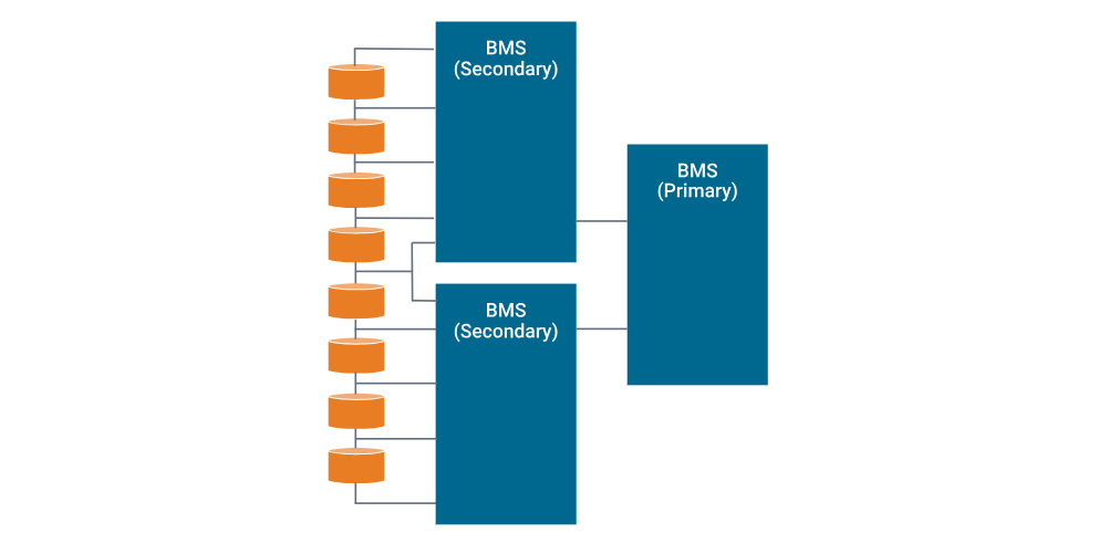
Conceptually comparable to the modular architecture, but, in this instance, the slaves are more constrained to only relaying measurement information, while the master is devoted to computation and control, as well as external communication. So, although like the modular kinds, the costs may be lower as the functionality of the slaves tends to be simpler, with presumably less overhead and less unneeded features.
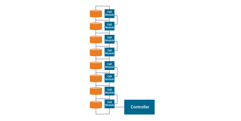
Distributed BMS Architecture
Considerably different from the other topologies, where the electrical hardware and software are encased in modules that interface to the cells via bundles of associated cabling. A distributed BMS includes all the electrical gear on a control board placed directly on the cell or module that is being monitored. This alleviates the majority of the cabling to a few sensor wires and communication cables between nearby BMS units. Consequently, each BMS is more self-contained, and performs calculations and communications as necessary. However, despite this seeming simplicity, this integrated form does make troubleshooting and maintenance rather challenging, since it lies deep within a shield module assembly. Costs also tend to be greater since there are more BMSs in the total battery pack construction.
The Importance of Battery Management Systems
Functional safety is of the utmost significance in a BMS. It is vital during charging and discharging operation, to prevent the voltage, current, and temperature of each cell or module under supervisory control from exceeding established SOA limits. If restrictions are exceeded for a period of time, not only is a potentially costly battery pack degraded, but deadly thermal runaway circumstances might result. Moreover, lower voltage threshold limits are also carefully monitored for the protection of the lithium-ion batteries and functional safety. If the Li-ion battery persists in this low-voltage condition, copper dendrites might ultimately form on the anode, which can result in heightened self-discharge rates and create potential safety issues. The tremendous energy density of lithium-ion powered devices comes at a price that offers little space for battery management mistake. Thanks to BMSs, and lithium-ion advances, this is one of the most successful and safe battery chemistries available today.
Performance of the battery pack is the second most significant element of a BMS, and this encompasses electrical and thermal control. To electrically maximize the total battery capacity, all the cells in the pack are needed to be balanced, which indicates that the SOC of nearby cells throughout the assembly are nearly equal. This is especially significant because not only may ideal battery capacity be reached, but it helps avoid overall deterioration and lowers dangerous hotspots from overcharging weak cells. Lithium-ion batteries should avoid discharging below low voltage limitations, since this might result in memory effects and severe capacity loss. Electrochemical processes are very responsive to temperature, and batteries are no exception. When ambient temperature lowers, capacity and accessible battery energy roll down dramatically. Consequently, a BMS may engage an external in-line heater that lives on, say, the liquid cooling system of an electric car battery pack, or turn-on resident heater plates that are mounted below modules of a pack included into a helicopter or other aircraft. Additionally, as charging of chilly lithium-ion cells is damaging to battery life performance, it is vital to first boost the battery temperature appropriately. Most lithium-ion batteries cannot be fast-charged when they are less than 5°C and should not be charged at all when they are below 0°C. For maximum performance during ordinary operational use, BMS thermal management frequently ensures that a battery runs within a restricted Goldilocks area of operation (e.g. 30 – 35°C). This ensures performance, promotes longer life, and supports a healthy, dependable battery pack.
The Benefits of Battery Management Systems
An whole battery energy storage system, sometimes referred to as BESS, might be made up of tens, hundreds, or even thousands of lithium-ion cells carefully packed together, depending on the application. These systems may have a voltage rating of less than 100V, but might go as high as 800V, with pack supply currents ranging as high as 300A or higher. Any mishandling of a high voltage pack might ignite a life-threatening, catastrophic tragedy. Consequently, thus BMSs are vitally necessary to assure safe functioning. The advantages of BMSs may be stated as follows.
- Functional Safety. Hands down, for big size lithium-ion battery packs, this is especially smart and needed. But even smaller formats used in, example, computers, have been known to catch fire and inflict massive harm. Personal safety of users of items that use lithium-ion powered systems offers limited space for battery management mistake.
- Life Span and Reliability. Battery pack protection management, electrical and thermal, guarantees that all the cells are all utilized within defined SOA requirements. This precise control guarantees the cells are taken care of against harsh use and quick charging and discharging cycles, and eventually results in a stable system that may possibly give many years of dependable service.
- Performance and Range. BMS battery pack capacity management, where cell-to-cell balancing is performed to equalize the SOC of neighboring cells throughout the pack assembly, enabling optimal battery capacity to be attained. Without this BMS capability to account for differences in self-discharge, charge/discharge cycles, temperature impacts, and general aging, a battery pack might ultimately make itself worthless.
- Diagnostics, Data Collection, and External Communication. Oversight jobs include continuous monitoring of all battery cells, where data recording may be utilized by itself for diagnostics, but is commonly purposed to the task for calculation to estimate the SOC of all cells in the assembly. This information is used for balancing algorithms, but collectively may be transmitted to external devices and displays to show the resident energy available, predict projected range or range/lifetime depending on current consumption, and give the condition of health of the battery pack.
- Cost and Warranty Reduction. The insertion of a BMS into a BESS raises expenses, because battery packs are costly and possibly dangerous. The more intricate the system, the greater the safety standards, resulting in the necessity for increased BMS supervisory presence. But the protection and preventive maintenance of a BMS regarding functional safety, lifespan and reliability, performance and range, diagnostics, etc. assures that it will drive down total expenses, including those associated to the warranty.
Battery Management Systems
Simulation is a crucial ally for BMS design, especially when utilized to explore and resolving design difficulties within hardware development, prototyping, and testing. With a realistic lithium-ion cell model in play, the simulation model of the BMS architecture is the executable specification recognized as the virtual prototype. In addition, simulation provides painless assessment of variations of BMS supervision functions against diverse battery and environmental operating conditions. Implementation concerns may be detected and explored extremely early, which enables performance and functional safety enhancements to be tested before implementation on the actual hardware prototype. This decreases development time and helps assure that the initial hardware prototype will be sturdy. In addition, various authentication tests, including worst case scenarios, may be undertaken of the BMS and battery pack when exercised in physically realistic embedded system applications.
We provide broad electrical, digital, control, and thermal hydraulic model libraries to assist engineers interested in BMS and battery pack design and development. Tools are available to rapidly construct models using basic datasheet specifications and measurement curves for numerous electrical devices and different battery chemistry types. Statistical, stress, and fault assessments provide verification across spectrums of the working region, including border regions, to assure overall BMS dependability. Furthermore, various design examples are supplied to assist users to initiate a project and rapidly acquire the answers required from simulation.